Translate this page into:
A novel device to micromanipulate oocytes during intracytoplasmic sperm injection

*Corresponding author: Kishor K. S. Bharadwaj, SpOvum Technologies Private Limited, Bengaluru, Karnataka, India. kishor.ks@spovum.com
-
Received: ,
Accepted: ,
How to cite this article: Bharadwaj KKS, Rokade SV, Yaswanth GB, Venkatraman V, Kumar P, Gupta B, et al. A novel device to micromanipulate oocytes during intracytoplasmic sperm injection. J Reprod Healthc Med 2022;3:6.
Abstract
Objectives:
To demonstrate a novel, non-pneumatic, compliant mechanism-based micro gripper to immobilize oocytes for the Intracytoplasmic sperm injection (ICSI).
Material and Methods:
The micro gripper is designed intuitively based on different techniques available to design compliant mechanisms in the literature such as the Stiffness Maps technique, Kinetoelastostatic maps, and feasibility maps techniques. The gripper’s holder was made from a 2mm thick PMMA sheet; whereas, the gripper was fabricated using a hydrophilic sheet, a proprietary material of 3MTM. The gripper and holder were assembled using a biocompatible adhesive.
Results:
Experimental trials carried out with the gripper holder on the ICSI workbench showed that the developed gripper holder was able to hold the oocyte gently and firmly in place. A micro linear actuator was used to actuate the gripper-holder. The device was tested for its efficacy to perform ICSI by designing ICSI experiments with matured oocytes and sperm; it was found that the degeneration rate was absolutely zero percent for all the matured oocytes.
Conclusions:
A novel device to micro manipulate oocytes during intra-cytoplasmic sperm injection is presented in this paper and is based on the gripping principle as opposed to the conventional suction-based pipettes for holding the oocytes gently and firmly in place during ICSI. The degeneration rate was found to be zero using the gripper-based novel device.
Keywords
Automation
Compliant mechanism
Microgripper
Micromanipulation

INTRODUCTION
Intracytoplasmic sperm injection (ICSI) is a widely practiced method of artificial insemination in the field of assisted reproductive technology. The development of ICSI, in 1992, has shown its significant and positive impact in treating male factor infertility.[1] The conventional ICSI procedure involves immobilization of the oocyte using a holding micropipette (inner diameter ~35 µm) or holding pipette (HP) by aspiration or suction technique. The sperm is injected into the oocyte using an injecting pipette (inner diameter ~5 µm), while the oocyte is being held by the HP. Despite the prevalence of ICSI as a mainstream assisted reproductive technique, the success rate of an ICSI procedure resulting in full-term pregnancy continues to remain between 30% and 35%.[2,3] One of the reasons attributed to the low success rate is the potential damage caused to the oolemma either during the oocyte immobilization process or during the sperm injection process.[4,5] Success of ICSI procedure depends on the skills of the operator as well as the quality of gametes. Specifically, when it comes to oocytes the quality depends on many factors including age and etiology of the patient. Sometimes, they are very fragile, sometimes with thick zona, large perivitelline space, and granular material around the membrane. They offer hardly any resistance while injection. There is always a possibility that they may get damaged. The best way to reduce weight is to hold the oocyte firmly with a good grip. Slight movement of the oocyte during the procedure may cause damage.
Investigations on alternative sperm injection methods such as piezo-ICSI, laser-assisted ICSI, and rotationally oscillating drill ICSI have been reported.[6-8] However, in all these reports, the oocyte is immobilized using the conventional HP which uses pneumatic – suction pressure to immobilize the oocyte. This method of immobilizing the oocyte can potentially create tension in the oolemma of the oocyte, thereby making it prone to rupture during the ICSI process. Moreover, any prolonged mechanical trauma to the oocyte membrane during the micromanipulation process could result in rapid cell lysis.[4,6] The HP itself is susceptible to breakage during the ICSI process and there is limited control over pneumatic parameters such as suction pressure of the HP. We believe that a minimally invasive and non-pneumatic method to immobilize the oocyte would be relatively safer and more effective in ensuring the integrity of the oocyte during the ICSI process.
The field of compliant mechanisms is currently being explored extensively in the area of biology, where beam-based mechanisms with varying scales are made and are used to manipulate micron level samples.[9,10] A compliant mechanism typically utilizes a flexible single-piece structure to transfer motion or a force from an actuator through elastic deformation of the flexible structure. Another important feature is the scalability of the compliant mechanism for a given application.[10-12] Herein, we demonstrate the application of a compliant mechanism-based microgripper. The microgripper is made of 3M™ 9960 Diagnostic Microfluidic Hydrophilic polymer material used to immobilize or micromanipulate an oocyte, thereby eliminating the requirement of an HP. The microgripper-based immobilization of an oocyte makes use of a cantilever structure with jaw-like features used for holding and manipulating the oocyte. The microgripper is designed with specific features which enable it to precisely control and immobilize the oocyte. The design of the microgripper-based ICSI system also involved the development of a suitable gripper holder, which transfers the actuation to the microgripper from the actuator.
Compatibility of the microgripper-based ICSI system with standard ICSI workbenches was ensured by designing the associated instrumentation such that the HP can be easily replaced with the microgripper and gripper holder unit. Just by changing the holding rod of the holder module, it can be used with any existing ICSI manipulator. In this work, ICSI experiments were performed with human oocytes and sperm, using the micro – gripper-based ICSI system to demonstrate its ability to perform a standard ICSI procedure. Our custom-made software allows the user to control the microgripper and also enables data-collection and processing of the information acquired during the ICSI process.
MATERIALS AND METHODS
Equipment
Intel core i3 processor of 8 GB DDR4 RAM (Intel NUC kit NUC8I3BEH) integrated with 10.1 inch USB powered LCD monitor with resistive touch (Neway – CL1010N)
Nikon Ti-S inverted microscope with high-resolution camera high-resolution CNB (G2960PF) camera and Sutter micromanipulators
Trackball with scroll ring from Kensington (K72337US)
Actuators from New scale technology: DK-M3L-1.8-TRK-6.0-S Developers kit
Vibration isolation Table (OptoElectronics Pvt. Ltd)
GCC LaserPro spirit series (12 – 100 W 10.6 µm sealed CO2 laser)
RI ICSI injection micropipettes with an inner diameter of 4 – 6 µm (from Cooper Surgical®).
Gametes and reagents
Matured metaphase human oocytes
G-MOPS pH stable media from Vitrolife for oocyte handling
7% polyvinylpyrrolidone (PVP) media from Vitrolife for sperm handling
Mineral oil – Ovoil™ from Vitrolife or Fujifilm Oil for Embryo culture (light mineral oil) from Irvine Scientific.
Methods
Preparation of ICSI dish
Take a clean and sterile 55 mm dish, make a droplet with aliquoted media (80 µL) four drops (droplet for oocyte)
Make a stick with sperm slowing solution (PVP media) 3–5 µL
Load the PVP solution with prepared sperm 8–10 µL in (sperm concentration should be 10–15 million/ml)
Connect the sperm droplet with the PVP media stick
Transfer the oocyte in the respective droplet
Make 2–3 flushing droplets of 30 µL and overlay with oil. The ICSI dish is now ready to be observed under a microscope for sperm jabbing.
DESIGN AND FABRICATION OF MICROGRIPPER-BASED ICSI SYSTEM
The microgripper-based ICSI system was designed to address two primary objectives:
-
Enable microgripper-based manipulation of the oocytes over the suction-based
HP or aspiration-based techniques
Collect the associated data in a seamless and coherent manner and process the same for novel insights.
[Figure 1] represents that the flow chart of the ICSI system and each block represents the hardware/software functional unit designed and developed in-house for the microgripper-based ICSI system.

- Flow chart of the microgripper-based ICSI system showing each functional unit.
The device can be primarily divided into four segments: The processor, an actuator module, the gripper holder, and the microgripper: A hydrophilic, biocompatible polymer that is designed as a consumable and the user shall change it for each patient as the material for grippers. The software to process the data was developed in-house. Furthermore, we describe the design and development of each functional unit of the microgripper-based ICSI system.
The gripper holder and microgripper design
The microgripper holder or gripper holder is made up of PMMA and is designed to transfer the force and displacement to the microgripper. The holder’s main function is to provide fixed support to the microgripper and to impart a linear actuation to the gripper from the actuator. The gripper holder is installed on the actuator module which, in turn, is seated on the HP holder of any existing ICSI workbench. The gripper holder and microgripper replace the HP and are used to immobilize the oocytes. It is envisaged that the gripper holder and the microgripper would form a combined unit through assembly and this unit shall be attachable to the actuator casing through snap-in support. The connecting rod of the actuator sits in the slot provided in the gripper holder when the linear actuator is actuated, it transfers the force and displacement onto the gripper holder in turn to the specimen handled. Both the gripper holder and the microgripper were fabricated using CO2 laser-based laser-cutting equipment (GCC LaserPro spirit series).
Gripper’s holder design and fabrication
The gripper’s holder is designed to control the microgripper which, in turn, holds the oocyte. The gripper holder structure is designed in AutoCAD Software and fabricated using a CO2 laser-based laser-cutting machine. The material used for its fabrication is a medically approved PMMA. The maximum height of the holder is 70.5 mm and the width is 45.68 mm, as shown in [Figure 2].
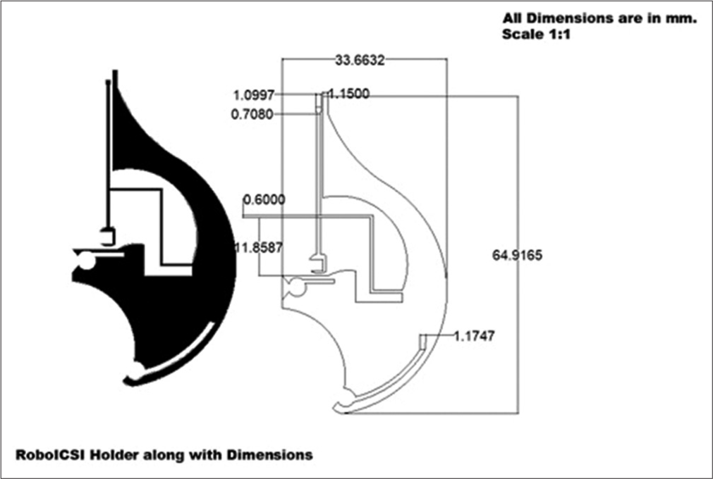
- Design of PMMA holder or gripper holder (All dimension are in mm with a scale of 1:1).
The gripper’s holder is shown in black colour for the reader to have a better understanding of its physical features. The dimensions, including minute details of the segments of the gripper’s holder are shown. The string-like structure in the middle of the holder is designed to manipulate the gripper to hold or release the oocyte. This string has a rectangular aperture at its base through which it is connected to the actuator so that its movement is controlled.
Microgripper design and fabrication
The microgripper is designed and developed to immobilize or gently micromanipulate the oocyte without causing damage to the cell. The microgripper structure is designed in AutoCAD software and the material used for its fabrication is the 3M™ 9960 Diagnostic Microfluidic Hydrophilic polymer. The microgripper footprint and the geometric dimensions are as shown in [Figure 3].
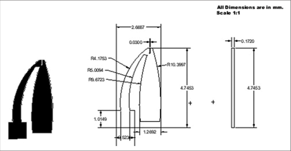
- CAD model of the silicone elastomer-based microgripper (All the dimensions used are in mm with a scale of 1:1).
A two-jaw structure similar to a plier was chosen for the microgripper design. This mechanism provides better control in holding or immobilizing spherical objects. The outer two arms of the microgripper perform the function of gripping or immobilizing the oocyte, while the third jaw at the center (which is stationary) renders ergonomic support to the oocyte during the ICSI process. The microgripper along with the dimensions is shown in [Figure 3]. In the design, the areas which are black in color represent the gripper, while the area represented in white color are the regions that were cut out by the laser cutting machine. The maximum height of the gripper was 6.9 mm (around 7 mm) and the width was 4.8 mm (around 5 mm). The microgripper is attached to the tip of the holder with the help of adhesive. [Figure 4] shows the assembly of the holder and the microgripper. [Table 1] shows the laser-cutting process parameters used during the fabrication of the holder and gripper.

- Assembly of the acrylic gripper holder and the 3M microgripper showing the fabricated device and the CAD model.
| Process parameter | Holder (PMMA) | Microgripper (Silicone) |
|---|---|---|
| Power (% of maximum power) | 30 | 0.3 |
| Speed (% of maximum Speed) | 0.8 | 0.1 |
| Resolution DPI (Dots per inch) | 1500 | 1500 |
| Resolution PPI (Pixels per inch) | 400 | 400 |
| Tool Path | X and Y direction | X and Y direction |
The actuator-module
The actuator module is mounted onto the ICSI workbench microscope, replacing the conventional oocyte – HP holder. The main function of this module is to actuate the gripper holder to hold or release the oocytes. The trackball is used for giving the user input through the processor for oocyte handling. Alternatively, the input can be provided using the graphical user interface (GUI). The actuator module contains 2 major components [Figure 6], namely, the actuator and the actuation rod.
Actuator
The actuator is a miniature high-resolution linear positioning system that has an integrated driver and works on a closed-loop system. It comes with a USB adapter, USB extension cable, and a flex extension cable [functional units are shown in Figure 5]. It has a travel range of 6 mm with a resolution of 0.5 µm and operates on the input voltage of 3.3 V. This actuator is packed inside a PMMA casing which is mounted onto an existing HP holder by fastening to the actuator module. The actuator’s linear shaft is perpendicularly connected to an actuation rod that actuates the gripper holder for micro-manipulating the oocytes. The actuator’s main functionality is to control the actuation rod movement.

- Assembly of the actuator module.
Actuation rod
It is a small projection on the linear acrylic shaft which is designed to control the motion to the gripper holder. The gripper holder is mounted to the actuation rod using a small slot present in the holder, as shown in [Figure 6].

- Assembly of the actuator module with gripper holder showing the anchoring points, actuation rod, and mounting rod.
The processing unit
The Intel NUC processor integrated with a 10.1-inch touch-screen LCD monitor was used to acquire specific inputs from the user either through the trackball or through the GUI on the LCD monitor. The processor also captures videos and images during micro-manipulation of the oocytes. The data collected by the processor were stored using our custom-made software for further analysis.
The trackball
The trackball consists of a ball and scroll ring. The gripper arms can be closed or opened by moving the trackball to the right or left, respectively, as shown in [Figures 7 and 8] and show the footprint of the gripper. The scroll ring is used to move the gripper holder unit up and down by moving the scroll ring in counterclockwise and clockwise directions, respectively.

- (a) Closing of gripper arms by moving trackball to the right and (b) opening of the gripper arms by moving trackball to the left.

- Footprint of the gripper attached to the holder.
EXPERIMENTS AND RESULTS
Experimental setup
The microgripper-based ICSI setup is assembled on a vibration isolation Table. As shown in [Figure 9], the gripper holder unit along with the actuator module device is integrated with any standard ICSI workbench with 3 Degree of Freedom manipulators such as a Narishige or RI or Eppendorf or Sutter manipulator and a standard inverted microscope (Nikon Ti-S), whose output can be viewed through a high-resolution camera. The actuator module is mounted on the microscope on the existing HP holder, on the left. It is connected to the processor through a USB cable from the actuator. The trackball is connected to the processor which enables the micro-manipulation of the microgripper and subsequently the oocytes.

- Microgripper based ICSI workbench.
ICSI experiments with microgripper
The microgripper is tested for its ability to immobilize matured metaphase human oocytes. The average diameter of a mature metaphase human oocyte is about 130 µm. [Figure 10] shows a matured oocyte immobilized using the microgripper. This demonstrates the ability of the microgripper to immobilize oocytes.

- (a and b) Immobilization of a human oocyte using microgripper.
Based on these observations, the microgripper-based ICSI device is investigated for its ability to perform an ICSI procedure. Matured human oocytes and human sperms are chosen for the ICSI experiments. The average diameter of human oocytes is ~130 µm.[13] The ICSI dish is prepared in MOPS media for handling the oocyte and 7% PVP media is used for the sperm sample. After the addition of the oocyte sample and the media in the ICSI dish, the dish is overlaid with mineral oil to prevent evaporation of the media during the ICSI process. The injection pipette is loaded with the sperm sample. The microscope is adjusted to bring the oocyte into focus and the gripper holder is aligned at an angle of 35° (which is the standard angular orientation of the HP in conventional ICSI workbenches). The microgripper is manipulated using the trackball to immobilize the oocyte for sperm injection. The sperm is injected into the oocyte while the oocyte is immobilized in the microgripper. [Figure 11] shows the immobilization of the human oocyte using the microgripper and sperm – injection using a micropipette needle.

- (a) Immobilization of a matured human oocyte using the microgripper and (b) sperm injection in the oocyte.
The oocyte is released by opening the gripper arms after sperm injection. We did not observe any significant deformation or degeneracies in the oocyte after the ICSI procedure.
Data collection and processing
A custom-made GUI is developed to semi-automate data collection and processing during the ICSI procedure. The data collection steps include: storing sample information (such as sample identification number and oocyte species), automated video-recording of the ICSI process after sperm loading, lossless video compression, and generation of event logs for multiple ICSI procedures. [Figure 12] shows the user interface which enables the user to record events during ICSI. [Table 2] shows the size of the video before and after compression.

- Representative image of the graphical user interface (GUI) on the LCD touchscreen monitor of the processing unit.
| Process: ICSI | Video 1 | Video 2 |
|---|---|---|
| Duration | 1 min 38 s | 0 min 37 s |
| Original Size | 46.1 MB | 9.73 MB |
| Compressed size | 8.47 MB | 1.4 MB |
The average time taken for an ICSI procedure is about 40 s.[14] [Figure 13] shows the event log captured from four ICSI procedures. Thus, the time taken for an ICSI procedure using the microgripper-based system is comparable to conventional ICSI systems. The fragility of the glass pipette is a challenging thing for any novice embryologist in doing ICSI using the HP; also, the harm caused to the oocyte due to the suction using HP is not negligible and the usage of a gripper can potentially solve this problem.[15]
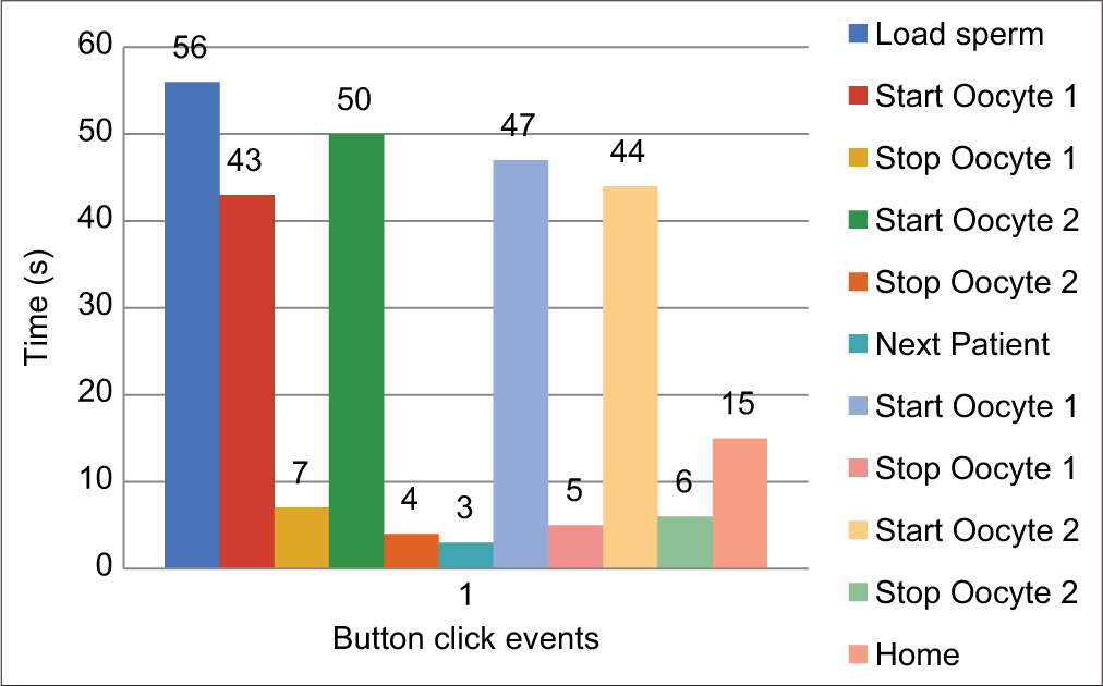
- Time recorded for each event after clicking the relevant function button during the ICSI procedure.
A total of 40 ICSIs were carried out on matured human oocytes and we found zero degeneration rate and the distribution of post ICSI oocytes and the embryo grading is as shown in [Figures 14 and 15] which show the graph which emphasizes the morphology-based health of the oocytes before doing ICSI. [Figure 16] denotes all the Nomenclature with abbreviations used in this article along with their full-forms.
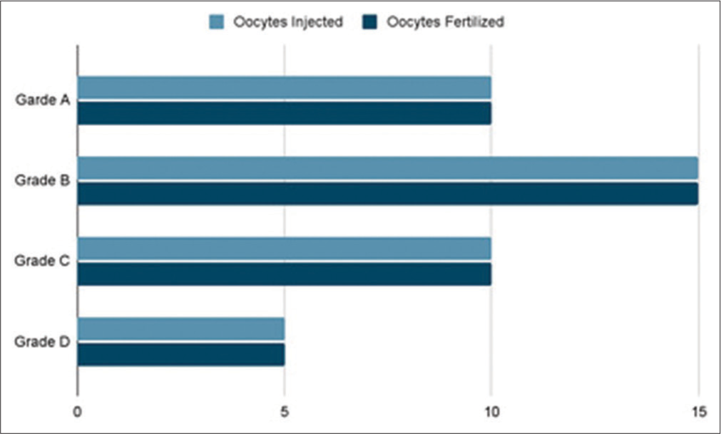
- Total number of matured Oocytes injected versus Embryo grading.
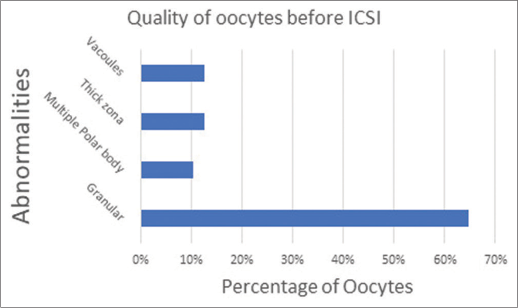
- Percentage of oocytes with their health-based morphology.
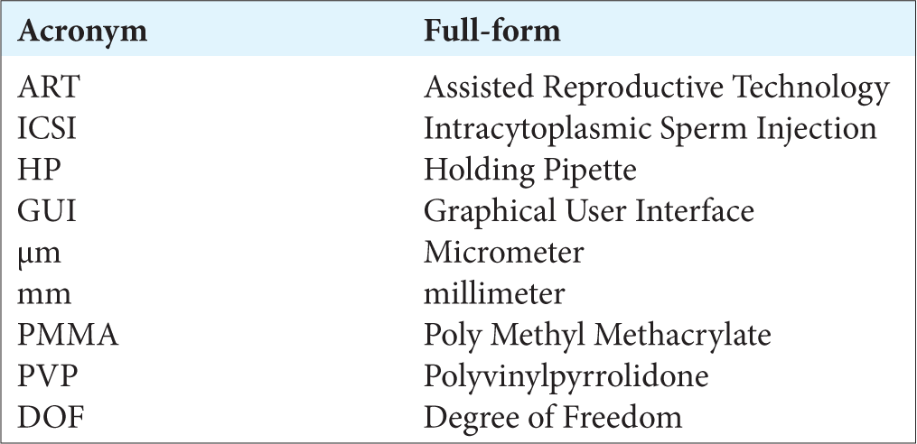
- Nomenclature.
Closure
The feasibility of using a compliant gripper for performing ICSI is demonstrated in this paper. The microgrippers and the parameters associated with its instrumentation are developed in coherence with conventional ICSI workbenches to ensure maximum compatibility with any standard ICSI setup. The microgrippers demonstrated their ability to effectively immobilize human oocytes and thereby successfully enabled ICSI. The ICSIs resulted in zero degeneracy and successful fertilization. Further, since the grippers are of non-fragile material, they can endure more than the regular pipettes and thus benefit embryologists in enabling more ease of handling. Setup time is considerably reduced since the gripper does not require any specific orientation, unlike the micropipettes. Furthermore, the framework collects data during ICSI that can benefit the user to retrospectively analyze and can result in better decision-making. A larger and multi-centric study with a larger set of data points is planned to further reinforce the efficacy of this novel approach of performing the ICSI procedure.
CONCLUSION
A novel device to micromanipulate oocytes during intracytoplasmic sperm injection is presented in this paper and is based on gripping principle as opposed to the conventional suction based pipettes for holding the oocytes in-place during ICSI. The degeneration rate was found to be zero using the gripper based novel device.
Acknowledgment
We thank Apoorva, Deepika Suma B N, Shweta Hegde, Deepak, Sampath Pavan Kumar, Tanay, Suhas, and Reshma for their help in successfully completing this work.
Declaration of patient consent
Patient’s consent not required as there are no patients in this study.
Financial support and sponsorship
Nil.
Conflicts of interest
There are no conflicts of interest.
References
- Pregnancies after intracytoplasmic injection of single spermatozoon into an oocyte. Lancet. 1992;340:17-8.
- [CrossRef] [Google Scholar]
- ICSI Outcome in infertile couples with different causes of infertility: A cross-sectional study. Int J Fertil Steril. 2013;7:88-95.
- [Google Scholar]
- Comparison of conventional IVF versus ICSI in non-male factor, normoresponder patients. Iran J Reprod Med. 2012;10:131-6.
- [CrossRef] [PubMed] [Google Scholar]
- Oocyte lysis following intracytoplasmic sperm injection: Association with measures of oocyte quality and technician performance. J Reprod Stem Cell Biotechnol. 2011;2:46-54.
- [CrossRef] [Google Scholar]
- Making ICSI safer and more effective: A review of the human oocyte and ICSI practice. In Vivo. 2016;30:387-400.
- [Google Scholar]
- Piezo-actuated mouse intracytoplasmic sperm injection (ICSI) Nat Protoc. 2007;2:296-304.
- [CrossRef] [PubMed] [Google Scholar]
- Laser-assisted ICSI: A novel approach to obtain higher oocyte survival and embryo quality rates. Hum Reprod. 2002;17:2694-9.
- [CrossRef] [PubMed] [Google Scholar]
- Visual feedback automation for ICSI with rotationally oscillating drill (Ros-Drill) J Med Dev. 2010;4:024502.
- [CrossRef] [Google Scholar]
- Micro-scale composite compliant mechanisms for evaluating the bulk stiffness of MCF-7 cells. Mech Mach Theory. 2015;91:258-68.
- [CrossRef] [Google Scholar]
- A micro-mechanical device for in-situ stretching of single cells cultured on it. J Micro Bio Robot. 2017;13:27-37.
- [CrossRef] [Google Scholar]
- Meiotic competence of in vitro grown goat oocytes. J Reprod Fertil. 2000;118:367-73.
- [CrossRef] [PubMed] [Google Scholar]
- Intracytoplasmic Sperm Injection: Indications, Techniques and Applications Berlin: Springer; 2018.
- [CrossRef] [Google Scholar]
- A novel technique of using mechanical grippers to immobilize embryo during biopsy. Fertil Steril. 2020;112:e291-2.
- [CrossRef] [Google Scholar]